
 |
|
|
|
#1
|
|||
|
|||
|
Over on the Seacraft Photos discussion BIGLEW suggested I offer photos of what I am doing. Long story - but here goes.
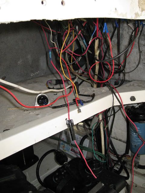
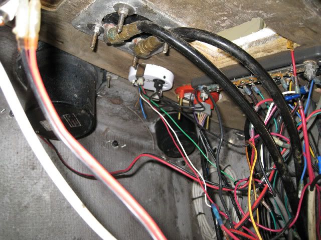
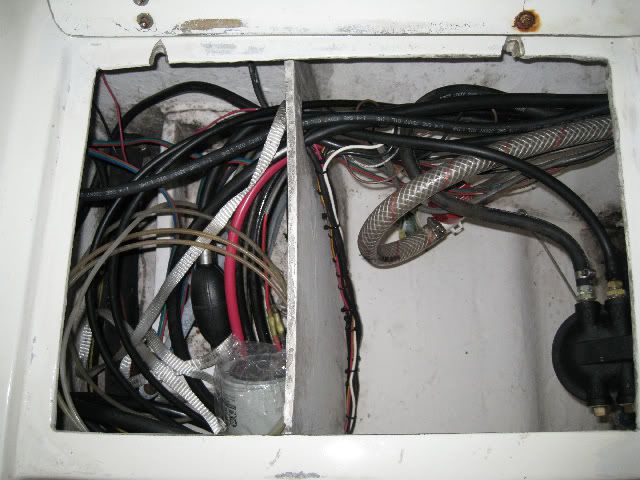
I sold a 1990 175 Yami on my 20SF a couple of weeks ago. Buyer came and I helped him remove the engine, harness, wiring, etc. I then went directly to my dealer - Beck's Outboard in Jacksonville (really good folks) - and had a 150 ETEC installed (Sweet, sweet engine). Somewhere, either on the Yami removal or the ETEC install, my trim tabs and fuel flow meter quite working. While trouble shooting, I found the power leads cut and/or disconnected. I began cutting tie wraps and tracing wiring. One thing led to another and the whole wiring bundle is now apart. My new GPS/sounder came in during this time and I decided to try and clean up the wiring haystack. So BigLew, et al, here is what it looks like today. I will post more as I move through this mess. Just know that I can't nail a nail in straight, cut a board straight, or open a tube of 5200 without covering me and everything around me with white goop - so please go easy on me as you view the progress!! This one is starboard aft transom 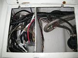 Under the console Under the console 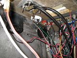 More under the console 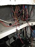
|
|
#2
|
|||
|
|||
|
I posted 640x480 size pics as noted in the instructions - looks like I could go larger and get a better look see. Anyone know what size will fill the width on the post without being too large?
|
|
#3
|
|||
|
|||
|
The images above are 120x160 so maybe the photo site you are using resized them smaller?
__________________
2001 23 Regulator 2006 F250 Yamaha |
|
#4
|
|||
|
|||
|
Well, actually, I resized them from the camera to 640x480 and then loaded them into photogallery. Maybe photogallery dropped them to 120. I'll play with it.
|
|
#5
|
|||
|
|||
|
Here are larger images of the original post
|
|
#6
|
|||
|
|||
|
Ron,
I respectfully suggest in the firmest of tones that you get yourself a copy of Nigel Calder's book, "Boatowner's Mecanhical and Electrical Manual". Hopefully your library, or their library system, can get you a copy. If not, it is an EXCELLENT reference book and is well worth it's cost (early Christmas/birthday gift) though not cheap. My copy has a SRP of $50, but I can tell you how to get it cheaper if you send me a PM. Anyway, the first order of business is to take a note book and write down EVERY electrical device you have; D/S, radios, tabs, nav lights, anchor light, under gunnel lights for night fishing---Everything. Then go to Nigel's book and begin to read about how he recommends to wire for the various systems and make notes/plans for each of the devices listed. Also include engine instument wiring if that did not come with your motor purchase. In Nigel's book in the 3rd chapter is an industry wiring color code chart for the wiring of individual systems, tach, oil temp, temp, oil pressure, etc.; get a copy of that, too. Run a string from you instrument panel to the transom area putting it up as if it was actually a wire. Run it to the furthest device and then measure it and write that down. This becomes a working length for calculating amounts of various wire. Go back to your list of devices and determine each device's wiring requirements and make detailed note of where it comes off the device and where the wire terminates at its opposite end. Depending on what device, etc. Refer to the color chart and determine if you should use a particular color for that device and start you shopping list. Note the type of connector required for each end; put those on the list. Do not forget fusing needs, etc. NOTE: If your eingine is wired now, things get a lot easier. Most of the real aggravation is in the sorting it out and planning stages. Talk to some of your knowledgable friends/professionals and get their input. If they look at you funny, tell them it is a project that you'd like to do yourself and ask for their advice/sanity check of your plan as if they are a "lifeguard" for the process. It might work. Once you've got that done and have planned gennerally how you are going to go about the actual work, get back to us. If you have any questions, do some searchs of the site here. There are some excellent photographs of real quality jobs and discussions to boot. Ask any questions you want as the process evolves. This could be really fun. Good luck and a take a deep breath. Slow, thoughtful and steady effort will conquer the challenge.
__________________
Getting home is more important than getting there! Plan accordingly! |
 |
|
|