
|
|
|
|
#1
 10-09-2009, 03:31 PM
|
|||
|
|||
|
I just re-wired my 23 over the winter. I couldn't even use the inside of my console because of the spider web of wires. After trying to trace a problem I gave up and took a pair of cutters to the mess. I filled a 5 gallon bucket with wires that were not used anymore - what a mess.
I would recommend a couple of things. A plan, a good length/gauge chart, heat shrink (duel layer), and copper coat (or equivalent) to keep the connections clean. Most importantly time. Dont rush the job - that will lead to mistakes or problems neither of which you want. Good Luck. 
|
|
#2
10-09-2009, 05:46 PM
|
|||
|
|||
|
I also have found numerous wire pieces taking up space and going nowhere! Spent time the last couple of days cutting and glassing in a mounting board under the console on the interior port side for my ground buss and fuse panel. I have a spreadsheet with all the equipment listed and assigned to a particular fuse and slot on the buss. I've got a new fused 6-switch panel wired and terminated. I am using heat shrink butt splices and terminals, and I soldered and covered teh solder connection with heat shrink on the switch panel. The heat shrink butt splices have the adhesive that flows when they are heated enough so no water can't get to the wire. I am trying to get as much of teh small, tight, connection work done on the bench before I mount things on teh board. I hate trying to work with wiring while on my back in an awkward position. I also pulled the transducer wire for my new GPS/Sounder from the stern to the console. I will try to post some pictures later this evening.
|
|
#3
10-09-2009, 06:25 PM
|
|||
|
|||
|
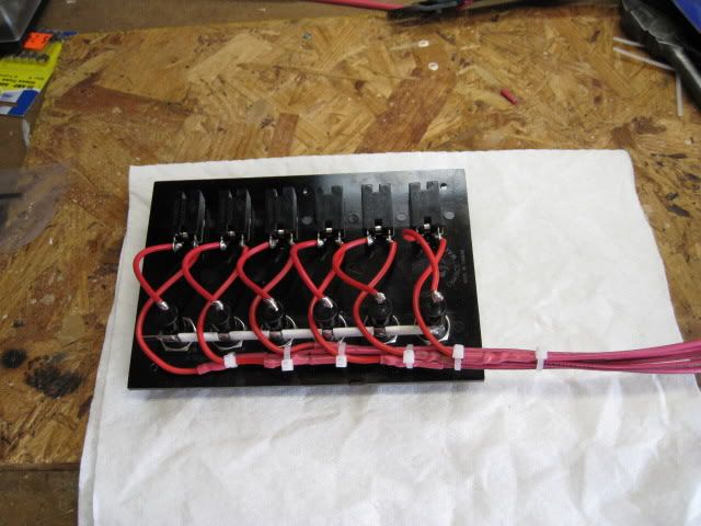
This is the back of the new switch panel. Each switch is fused. All the terminals are heart shrunk. This will be tied into the power buss on the fuse panel. A separate ground buss will be mounted on the backboard with the ground lead position for a piece of equipment on the buss matching the panel position location for that equipment.
 This is the fuse panel. I am using this for equipment that does not need an on/off switch. It incorporates a ground buss right on the panel which I like. I can have the power and ground for an item use the same position on the panel. This makes for ease of location and troubleshooting or removal. 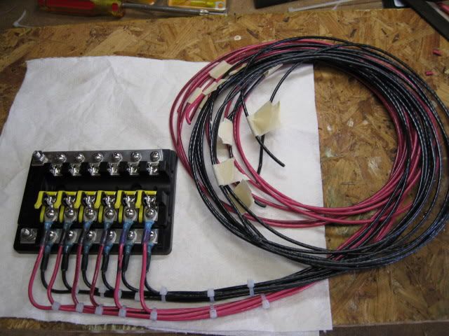
|
|
#4
10-09-2009, 08:13 PM
|
|||
|
|||
|
Ron,
WOW, I think you are holding out on us regarding your skill level! It looks very neat and professional!!!!! FWIW, cable color coding is the only thing I don't see and that is likely because the devices concerned do not have a special color ID associated with them. It is a very minor point and i make it only in a general way. "Drip loops" assure that any condensed moisture/water runs DOWN away from the terminals and either drip where it cannot cause/contribute to any deterioration of the terminal connections and I seldom see it used. Very professional looking, very much indeed. CONGRATS!
__________________
Getting home is more important than getting there! Plan accordingly!
|
|
#5
10-09-2009, 11:54 PM
|
|||
|
|||
|
BigLew thanks! Actually for the switch panel, I have a VHF, GPS/sounder, livewell pump, running lights, anchor light, and bilge pump. All of them are red and black wires from the unit. The fuse panel will handle power for the Porta-Bracket, trim tabs, 12 volt accessory plug (cig lighter), fuel gauge, fuel flow gauge, and fused power for the engine hour meter and voltmeter. That leaves me two spare fuses for anything else that might be added in the future. What that would be at this point I dont know.
I am indeed away of a drip loops used them all the time with outside wire in the telephone industry. They will be there when the panels are mounted.
|
|
#6
10-10-2009, 01:55 AM
|
|||
|
|||
|
Looks good to me - kinda like mine - easy to trace wires, they wiggle when you pull on them

__________________
Any way you measure it - dumbass is expensive
|
|
#7
10-10-2009, 02:39 AM
|
|||
|
|||
|
Looks like you're doing just fine...
Nice plan. Keep it simple.Look forward to seeing the balance of the project. 
__________________
there's no such thing as normal anymore...
|
|
#9
10-20-2009, 12:17 PM
|
|||
|
|||
|
Thanks Will. I have been remiss in not updating this deal. I did finish out what I wanted to get done. The wiring, with a couple of exceptions, had been replaced about three years ago. The only wire I totally replaced was the bow navigation lights - they were toast.
This image is the backboard I glassed to the port inside of the console. I mounted a six position fuse panel - it has its own ground buss - and a separate ground buss that serves the switch panel on the console. The extra coil of wiring is the tag ends for the unused fuse positions. This way if I add something in the future I won't have to be taking the wiring all the way to the fuse panel. I can pick up the battery and the ground leads off the coil and splice them in. BTW I used heat shrink splices that are totally waterproof in about half the connections (mainly the smaller wires). I used soldered connection with heavy heat shrink on the others (mainly the larger wires). I find that splices do not hold well on wire larger than than about 12 gauge. 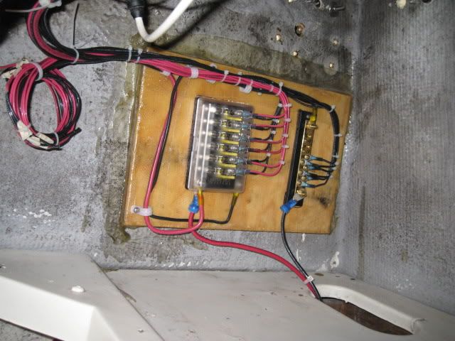 When you compare this next photo to the original you can see the work. The cloth looking strip is a piece of Kevlar strapping that the phone company uses to pull cable through an underground duct. It is extremely flexible, small, and yet has an 1800 pound breaking strength. I found it next to a pit they were working in and they gave it to me. I have it in place from the transom to the console. There is enough there that I can tie it together into a continuous loop. If I need to pull more wiring, I use the loop and pull it through and the tape stays in place for the next wiring job. 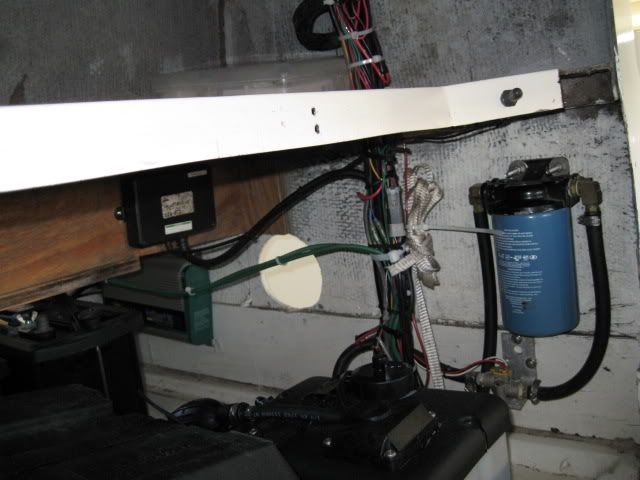 This is the transom part of the wiring. You can see the other end of the Kevlar tape in the bundle. That tape was a life saver! All the black looking stuff on the left side of this pic is simply dirt/grease/oil. I am in the process of cleaning all that up as well. 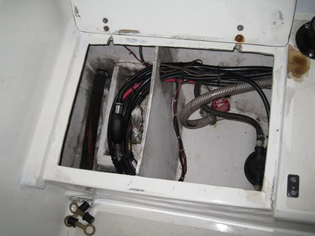 The neat part is that I now have a ton of room under my console on the shelf, and more importantly, everything works!! Actually, everything worked the first time with no mistakes! I amazed myself! I have a spreadsheet with 4everything listed by terminal number, switch number, and if applicable, wire color. Thanks for everyone's encouragement. Had I not found CSC I would probably have lived with the mess!
|
|
#10
10-20-2009, 08:31 PM
|
|||
|
|||
|
Wow...nice job Ron. I like how you roughed the switch panel before installing...makes it very neat and clean!!
__________________
__________________________________________________ ________________ 1974 23SF
|
 |
| Thread Tools | Search this Thread |
| Display Modes | |
|
|


 Hybrid Mode
