
|
|
|
|
#1
 01-15-2012, 05:28 PM
|
|||
|
|||
|
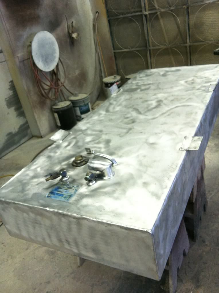
Got back to work on the boat friday and today. The starboard stinger top was cut off, and the old foam was dug out. As a whole, the foam was wet, but it was only fully saturated at most, the bottom inch or so a few feet from the stern. Its very misleading when you open up the stringers and start to dig because the top portion is very dry. I would estimate total amount of weight removed was 50-80lbs. I used a sharpened putty knife to cut out the foam located where the stringer meets the hull. Then I drilled some drain holes as close as I could to the bottom of the stringers and lifted the trailer hitch 40" or so off the ground and washed the stringers out. Let it dry overnight and cleaned the inside with acetone before pouring the foam. Side note:the tank cleaned up great.
 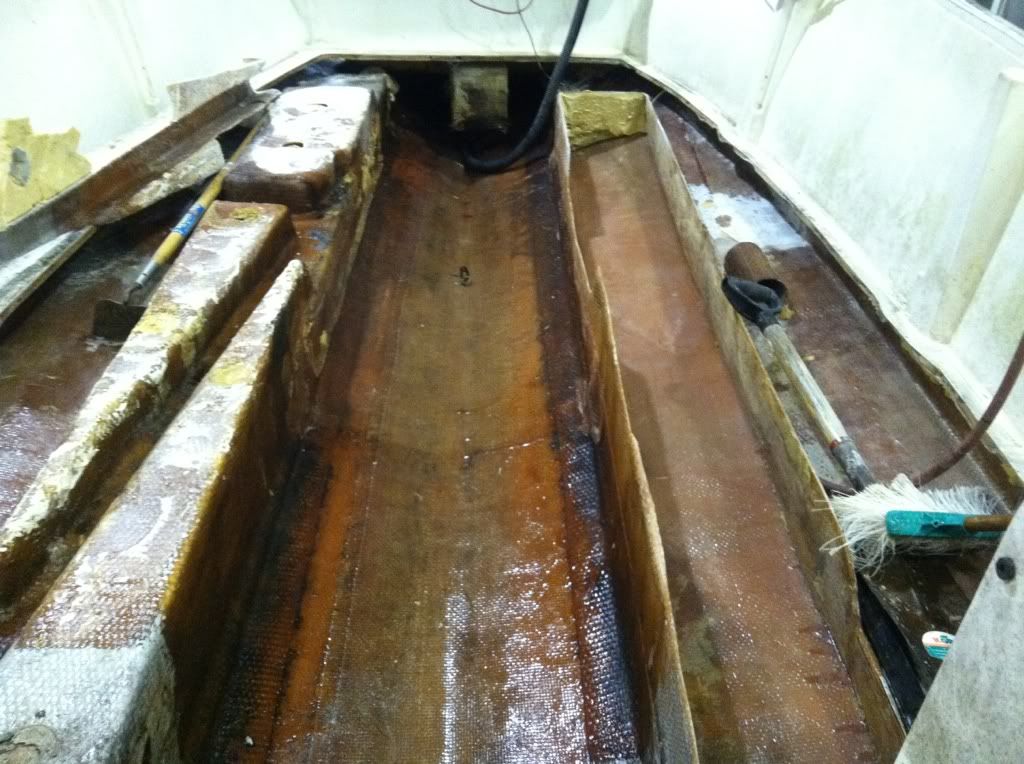 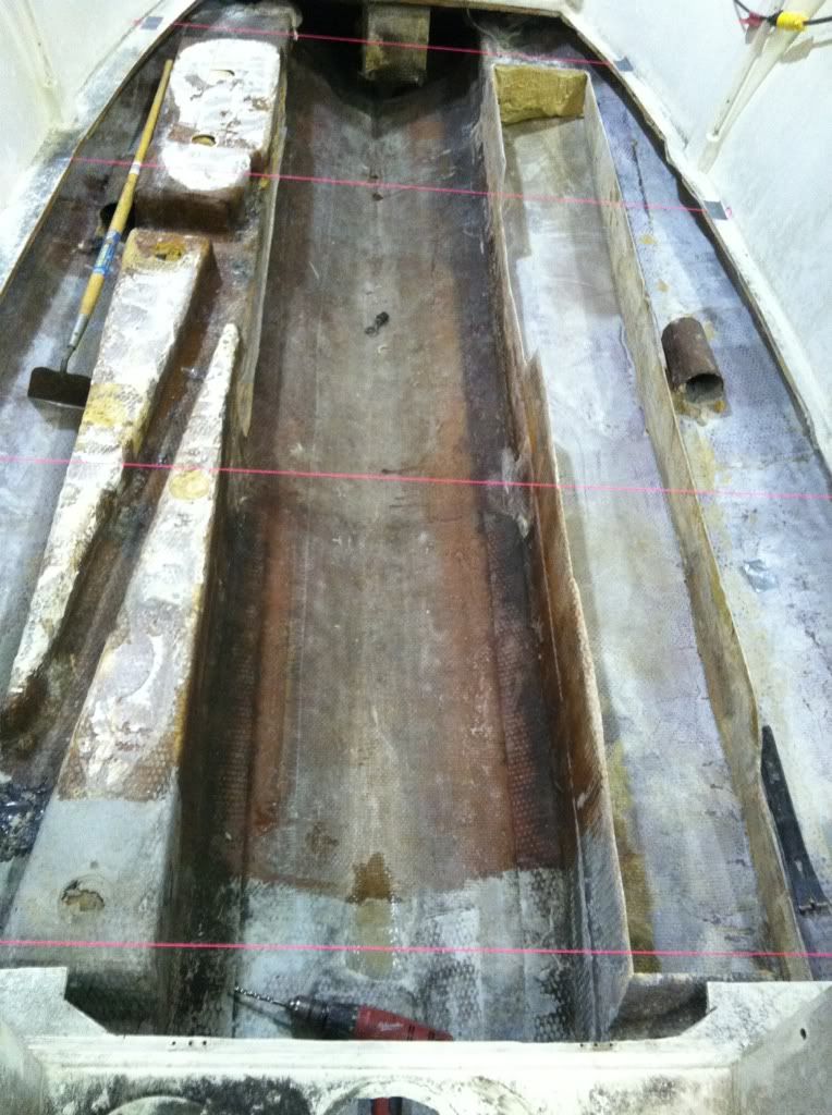 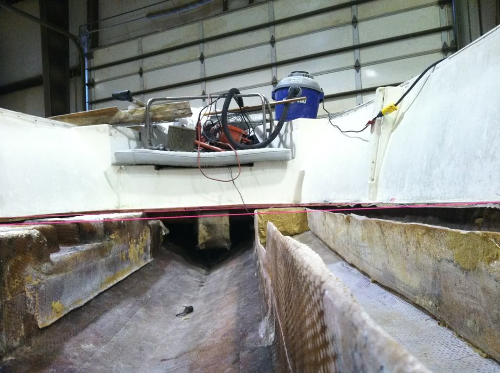 My plan to compensate for a raised deck (1/2" -5/8") goes as follows. The foam poured in was 3/4" less than the top of the existing deck height. Glass 1708 over the foam, place 3/4" mg ply on top and glass 1708 on top of that. The final height should be right at the existing deck height. The foam was poured in once I created a "shell" for the foam to form to. The shell was made out of 3/4" melamine and screwed into the sides of the stringer. Once the foam was poured in, I screwed the cap of the shell on. NOTE: all of the melamine had PVA release film rolled onto it so it popped off easily. MAKE SURE TO GRIND THE FOAM TO REMOVE THE PVA WHEN FINISHED. Seems like a no brainer, but NOTHING will stick to the PVA, so it needs to be removed. The neon colored string was used as a template for the 3/4" melamine shell. Once the foam was all set, I popped the shell off and ground the foam where it needed it. I only did one stringer at a time, because I was concerned with excess hull flex. As the picture shows, I poured the foam, not leaving any area for a pipe chase. Im going to cut the pipe chase in and it will be at a 45* instead of running the length of the stringer. Seems like a lot of lost support area for the deck having the chase run down the length of the stringer. I plan on having the other stringer done by this week so I can get started on tank bulkheads/supports next weekend. 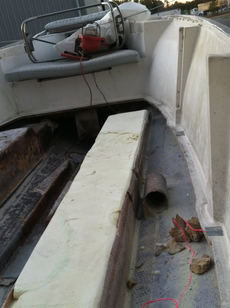  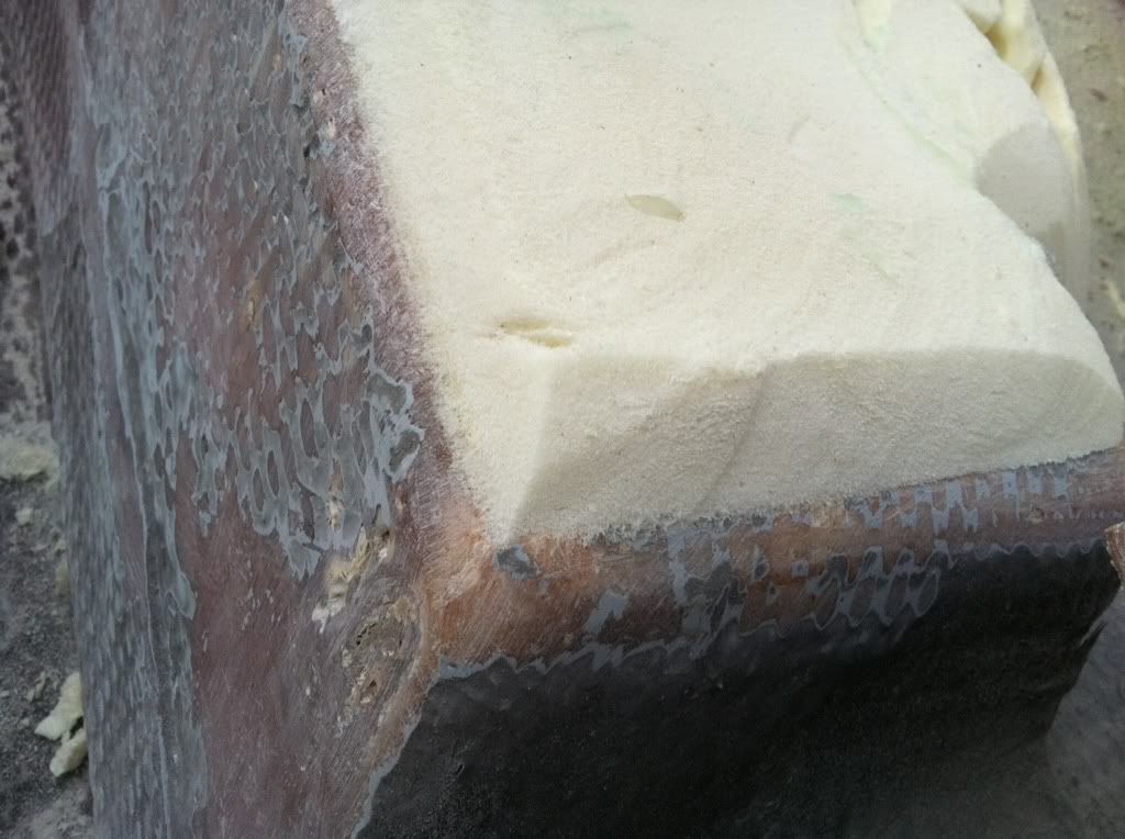
Last edited by alexh; 01-15-2012 at 07:09 PM. 
|
|
#2
01-16-2012, 08:58 AM
|
|||
|
|||
|
Nice work. I'm following this closely as I, too will be going through this process one day. Hopefully, not too soon, though.
__________________
1975 SF18/ 2002 DF140 1972 15' MonArk/ 1972 Merc 50 http://i833.photobucket.com/albums/z...photos/SC3.jpg
|
|
#3
01-24-2012, 08:54 AM
|
|||
|
|||
|
Still working the stringers. Poured the port side stringer Friday and ran out of foam so I had to make an hour plus drive to go pick up more before I could continue. Picked up more poly resin so it wasn't a total waste of time. The port side stringer was VERY dry, and probably didn't need new foam but I'm not going to chance anything. Once the foam was set I sanded/shaped the foam to give the edges a radius so the 1708 could form to it. I cut in the 45* channels for the pipe chase as well. A wire wheel with a 3"+ diameter makes good inside corners for the pipe chase channel. Tracker used a heavy weave glass so sanding with a pad sander/DA only hit the high spots on the weave. Using sandpaper by hand allowed for the entire surface to be roughed up, which ate up a lot of time.
The 3/4" ply thats going to lay on top has been cut to size, has the top edge rounded and is hotcoated already. I'm going to mix up some cabosil and resin and bed the ply to the stringer top this week. Bulkheads and glassing in a 3" pvc pipe cut in half are also on the agenda. stringer cap cut/pulled off 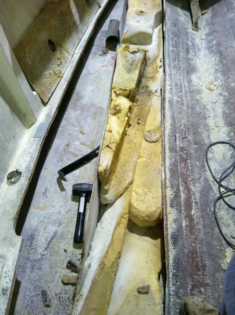 Glass cut to fit/corners cut to fold properly 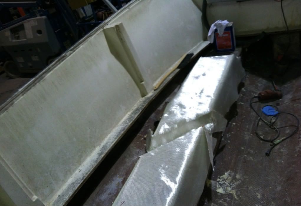 Glassed. 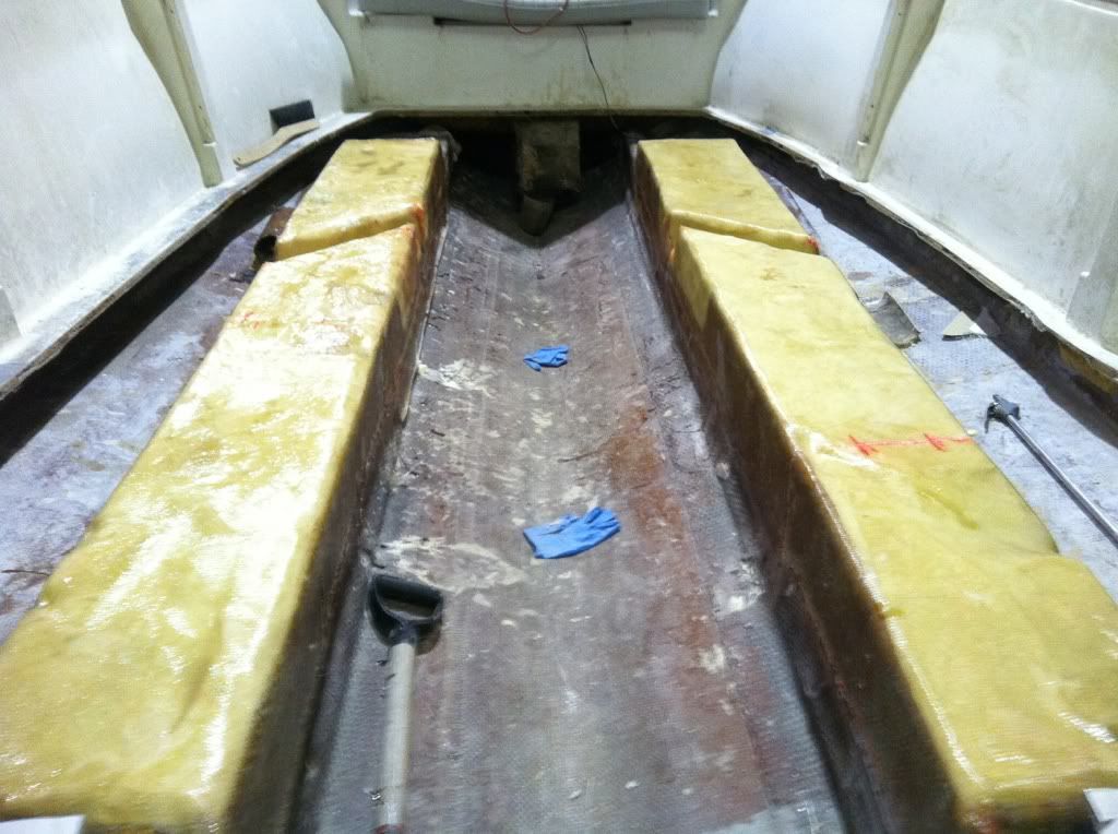 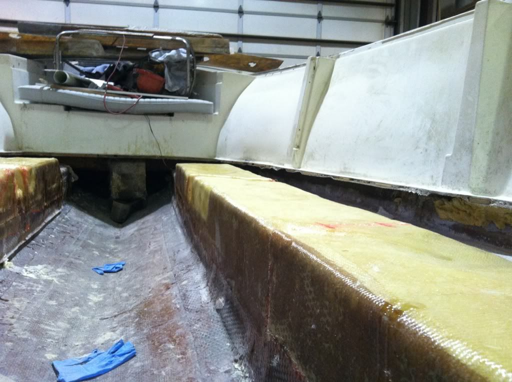
|
|
#4
02-08-2012, 12:26 PM
|
|||
|
|||
|
I have attached a PDF of my proposed plan to reinstall the fuel tank. (not to scale/estimated measurements) I have extra bullet proof material (1/2" and 1 1/2") laying around from previous jobs, which is just layers of fiberglass/kevlar with poly resin. My plan is to create a perimeter "base" for the tank to be bonded to via 4200 and use the existing tabs to screw into the stingers as before.
Questions: -The goal is to leave as much tank as possible exposed to air, but do you think there is enough support with the tank being supported by the perimeter? -I have some 1/2"x2" neoprene material. Should that be used on the bottom of the tank to mount to the perimeter? I do not understand the benefit of neoprene if the tank will be bonded to the cleat material, which will be glassed to the stringers. I really feel like this will be enough support. If a full tank plus tank weight is at max 350lbs. and there is roughly, at a minimum, 1" of coverage on the tank/cleat perimeter then...48"+48"+24"+24"=144 in^2. 350lbs spread over 144in^2= 2.43lbs/in^2 Doesn't seem like much of an issue as long as the tank DOESN'T MOVE. I think the beating and banging of a loose tank will destroy any sort of mounting system. Open to any and all criticisms. I've currently got the front tank bulkhead installed, and another bulkhead just forward of the stern bait well. I purposely left the rear tank bulkhead out because I had yet to get my head around reinstalling the tank, which I plan to do this weekend. Ill have pictures up this weekend of current progress.
|
|
#5
02-19-2012, 03:45 PM
|
|||
|
|||
|
Just some more progress photos.
Fillets made so the 1708 can wrap the stringers: 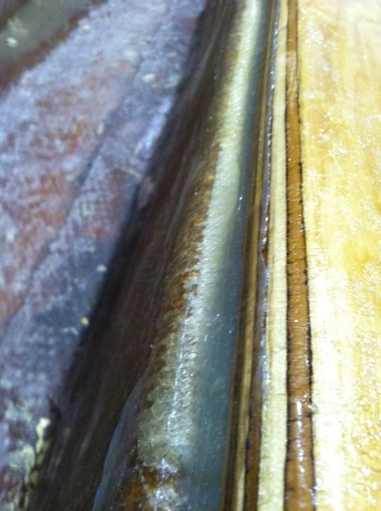 A little blurry, but this is just after the stringers with plywood were capped with a final layer of 1708: 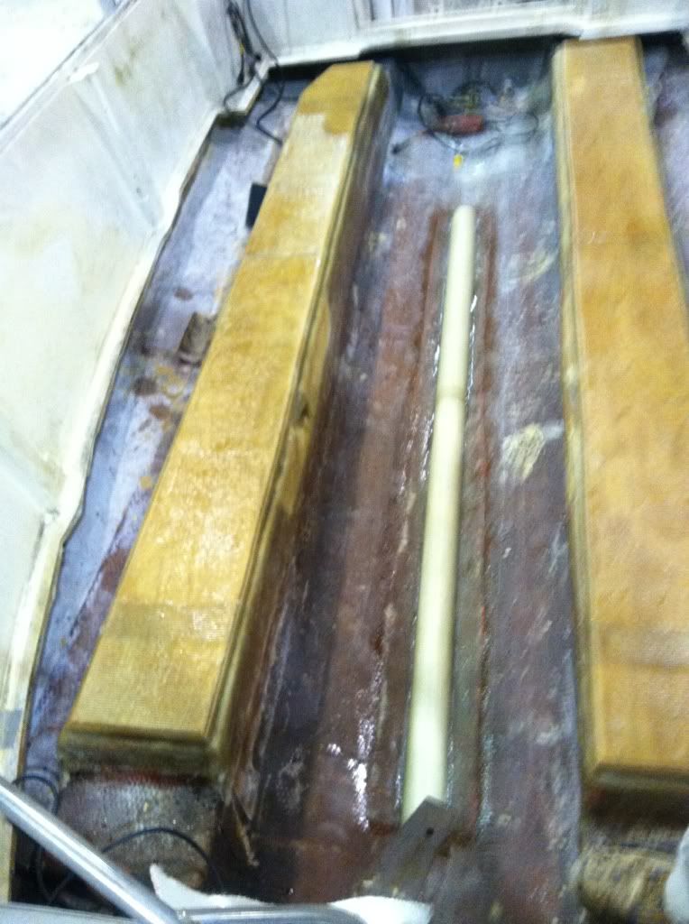 The next photos show the bullet proof material I used at a lip for the tank to sit on. One edge was radiused in order for it to conform to the angle where the stringers and hull meet. I made up a big batch of cabosil, milled fibers and resin to bed the pieces properly. I then laid strips of 1708 on top and back up the stringer for added strength. 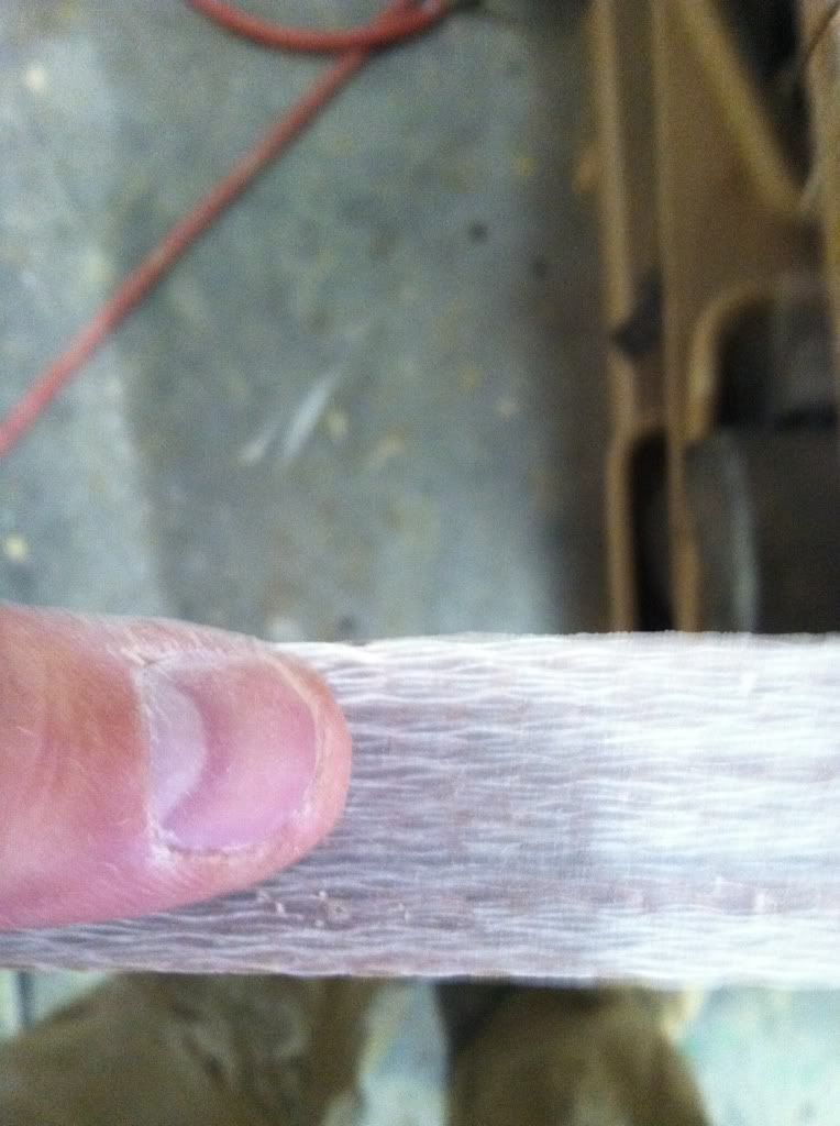 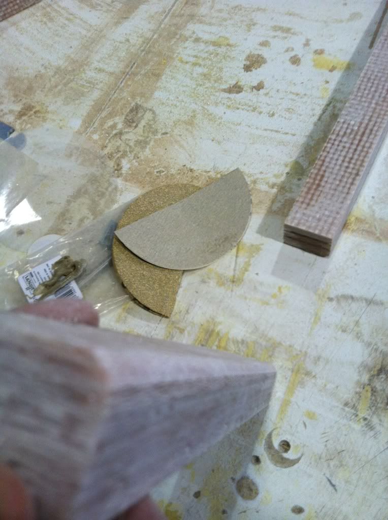 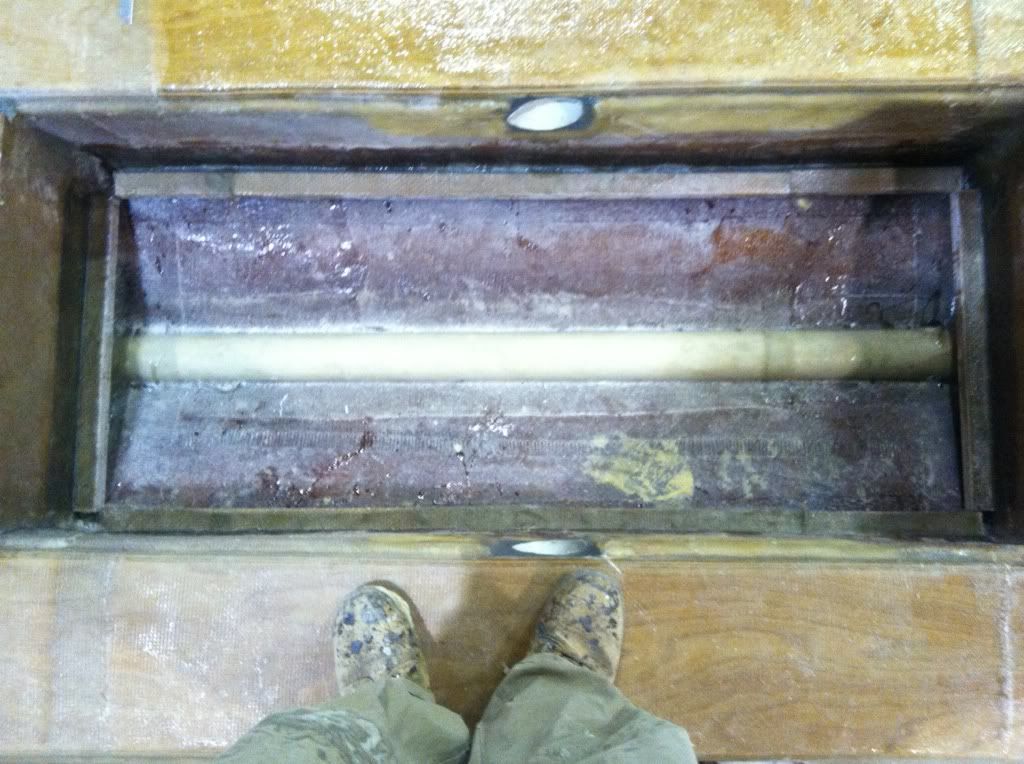 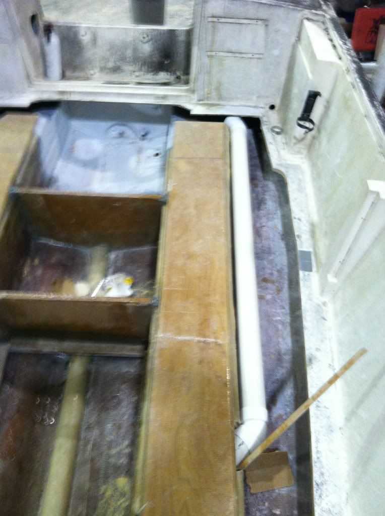 The pvc pipe chase is not fastened in yet, but will be shortly. I primed/painted the area in front of the tank and bilge area with urethane paint. The front area will have the hatch shown and act as the anchor locker. The pvc along the keel starts at the bulkhead and runs to the bilge for drainage. 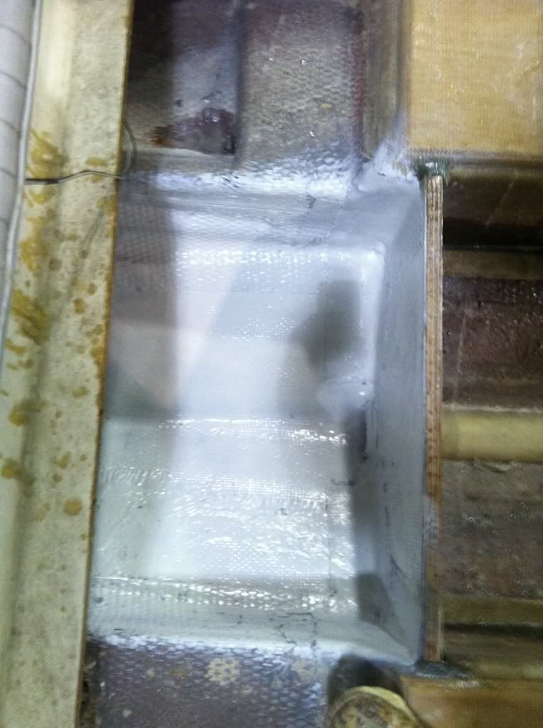 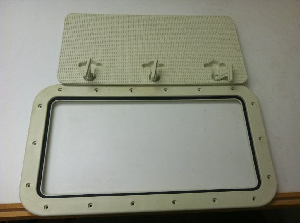 The thru hull pad was bedded and covered in 1708 before the urethane paint. I over drilled the holes and refilled them thickened resin, in hopes of eliminating any chance of water intrusion. 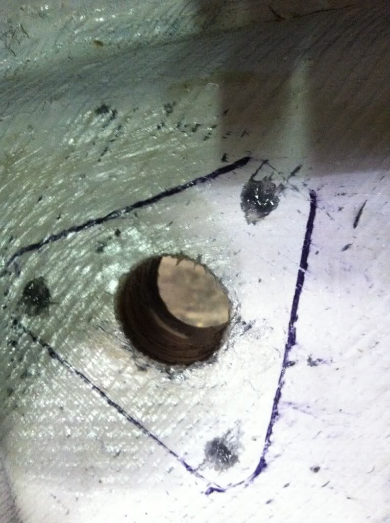 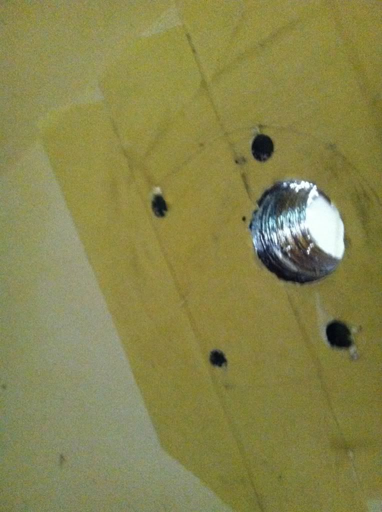 Ill pull the tape on the inside area of the scoop once the resin is hardened. I'm following the same process as shown on boe marines website for installing a thru hull transducer. The tank is ready to be set, but I'm not going to do that until Ive got the areas outside of the stringers foamed in. Fuel lines are on the way.
|
|
#6
02-27-2012, 08:31 AM
|
|||
|
|||
|
Templated the deck and got it cut out with extra blocking where there are seams/cutouts. Still awaiting a date for the foam to go in (hopefully this week).
Template made from scrap 1/4" material. 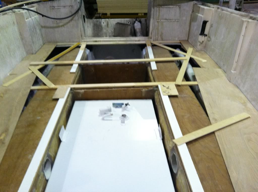 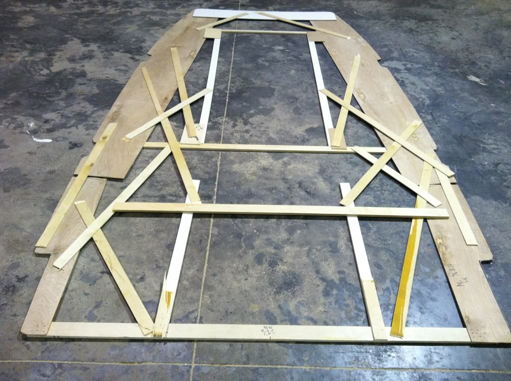 spraypainted the outline onto 1/2" MG ply. 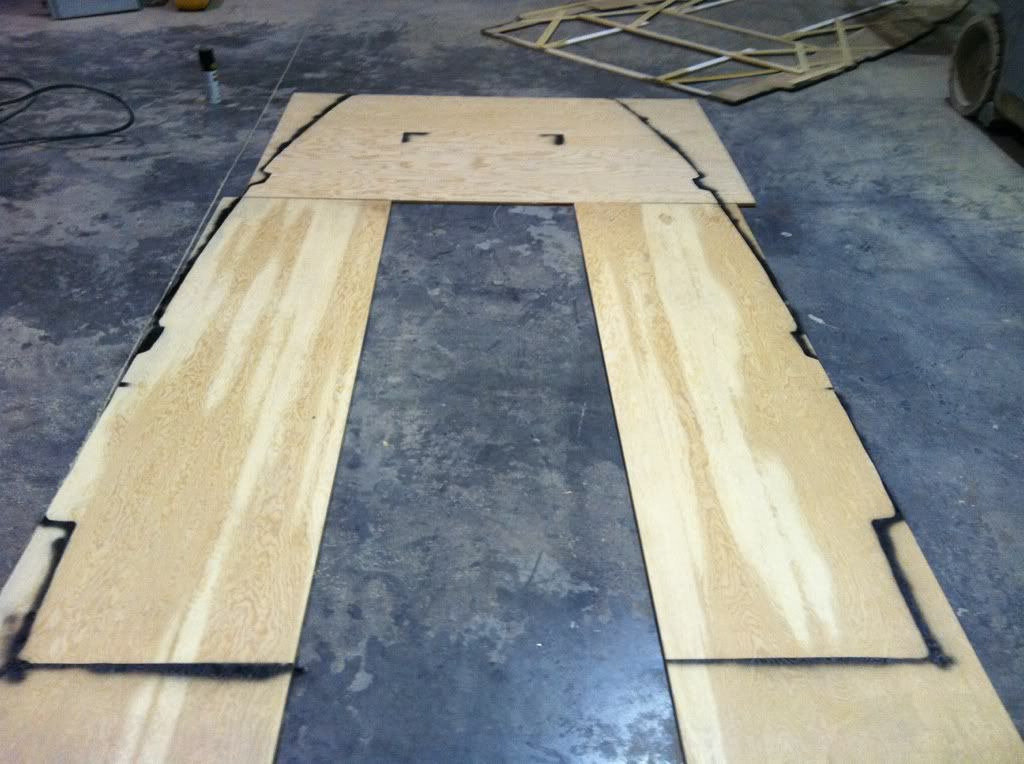 cut out, with a 3/8" radius on the underside @ the perimeter, and test fitted. 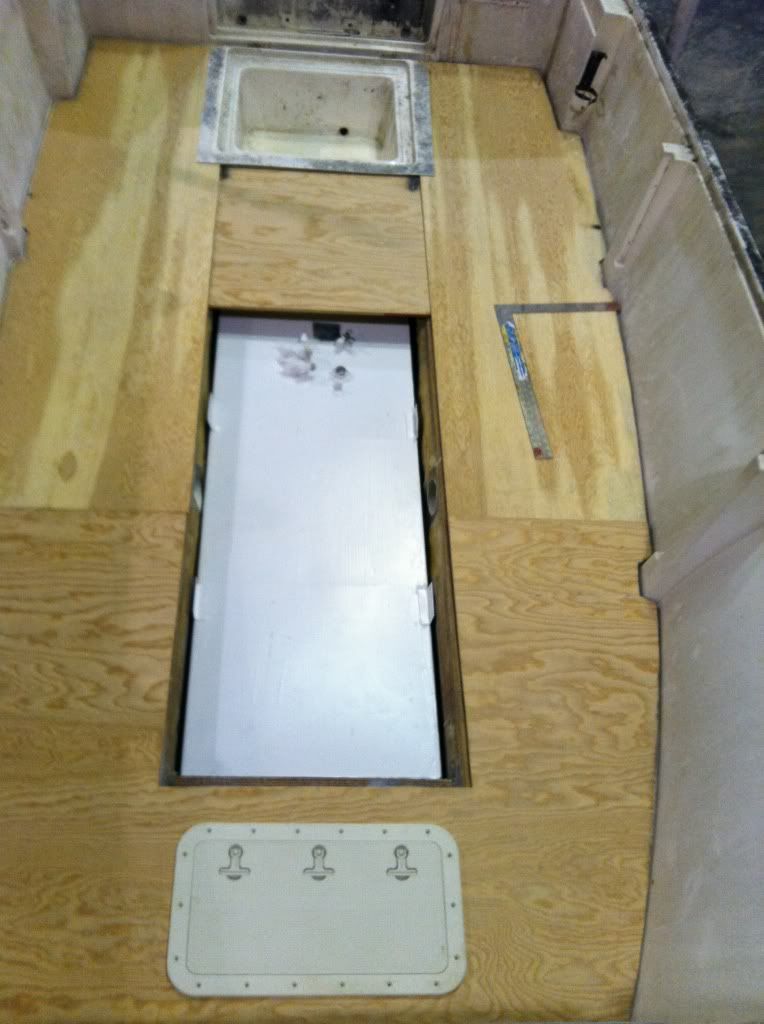 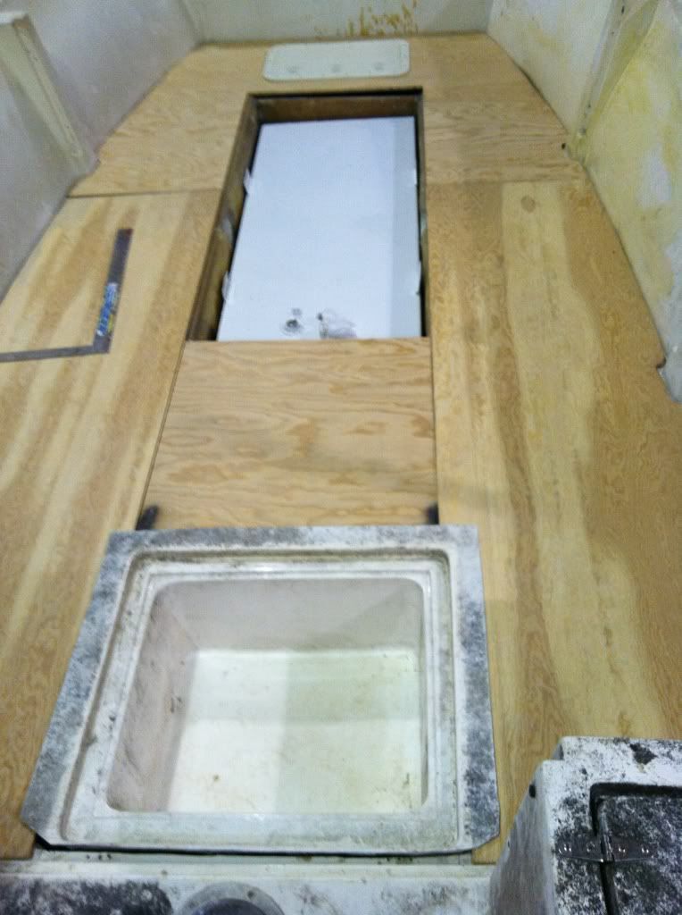 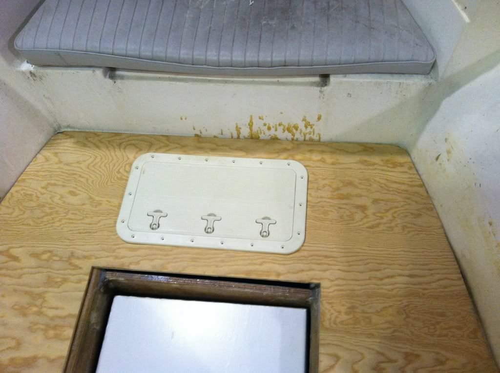 The above pic shows the area for anchor storage and the hatch. The piece of ply in the middle right behind the fuel tank was swapped for a wider piece so it can get plenty of support from the stringers. As it is in the picture shown, there isn't enough support left/right of the wood, as it barely touches the stringers. This pic shows the available room for the wire chase, something I was originally concerned with, but its fine. 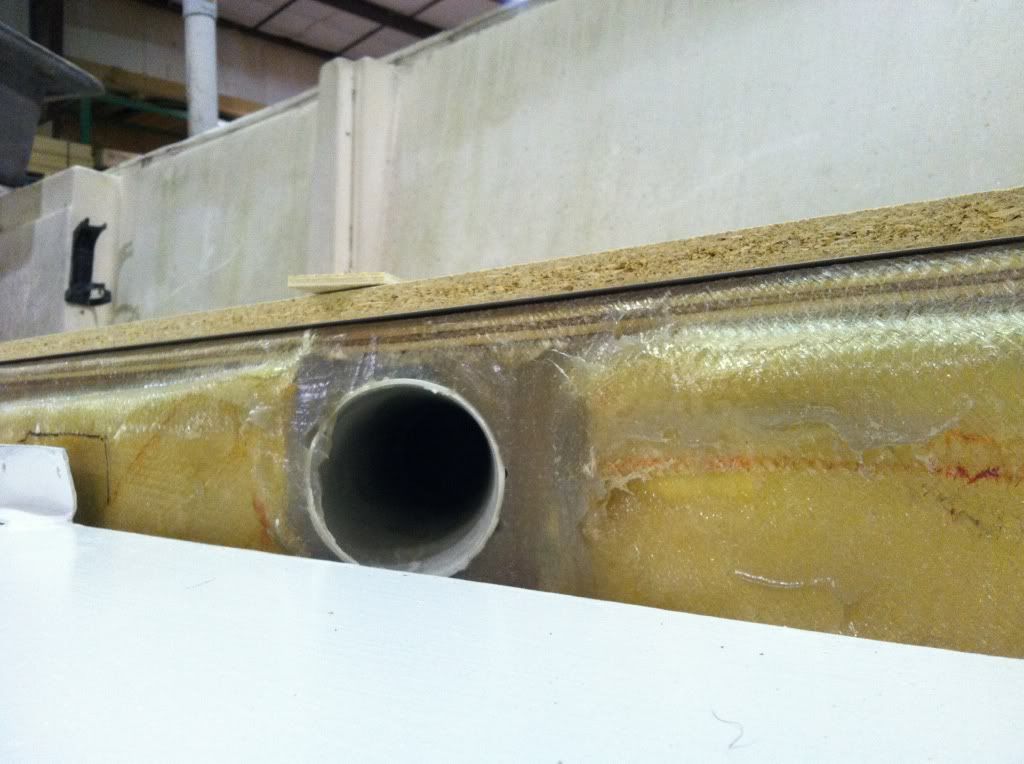 Hotcoat and glass the underside is on the agenda this week. Pretty busy with a lot of other stuff, so we'll see what gets done.
|
 |
|
|


 Hybrid Mode
